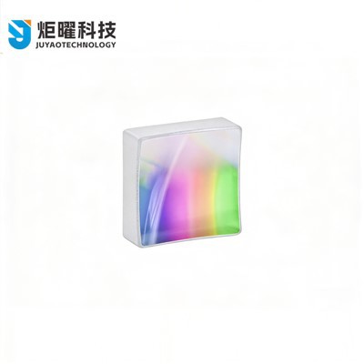
Diffraction Gratings
Optical dispersive elements · Spectroscopy · Lasers · Telecom · Source: PhotonLab
Diffraction gratings are key optical components in a wide range of applications, including spectrometers, other analytical instruments, telecommunications, and laser systems. A grating contains a microscopic periodic groove structure that splits incident light into multiple beam paths through diffraction, causing light of different wavelengths to propagate in different directions. This makes a diffraction grating functionally similar to a dispersive prism, although a prism separates wavelengths by wavelength-dependent refraction rather than diffraction (Figure 1).

Figure 1. A dispersive prism separates wavelengths by refraction (top), while a diffraction grating separates wavelengths by diffraction due to its surface structure (bottom).
Light incident on a grating is diffracted according to the grating equation:
Here, m is an integer describing the diffraction (or spectral) order, λ is the wavelength of light, d is the spacing between grooves on the grating, α is the angle of incidence, and β is the diffracted angle of light leaving the grating. Constructive interference of different diffracted wavefronts occurs at integer multiples of the wavelength, which is why "m" appears in Equation (1). m defines the diffraction order: m = 1 is called first-order diffraction, m = 2 is second-order diffraction, and so on (Figure 2). If m = 0, the light is either directly reflected from the grating or transmitted through it, depending on whether it is a reflection or transmission grating; this is called zero-order diffraction. Unlike a dispersive prism, shorter wavelengths are always closer to the directly reflected or transmitted light-in this case, the 0th order. Some overlap exists between different orders. All angles are measured from the grating normal (perpendicular to the grating).

Figure 2. Some light is reflected directly as 0th-order diffraction, while other parts of the incident light are diffracted into first-order angles depending on wavelength. Smaller amounts are separated into higher-angle 2nd- and 3rd-order diffraction.
What to Consider When Choosing a Grating
When selecting a grating, it is important to specify the wavelength range, the blaze wavelength (the wavelength with the highest efficiency in the diffracted spectrum), and the blaze angle. The blaze angle describes the first-order diffraction angle of the blaze wavelength. At this angle, α and β in Equation (1) are equal, and the incident light is diffracted back in the direction from which it came. This condition is also called the Littrow configuration. Operating close to this angle gives the highest efficiency.
Groove density, or groove frequency, is usually specified. It is the inverse of the groove spacing d. A key property of an optical system is its dispersion, but this depends on both the grating's properties and how the grating is used. Without other system details, a grating alone cannot be assigned a rule such as "a certain rotation corresponds to a certain wavelength separation." A grating's resolving power may also be specified, and it relates to the system's spectral resolution. However, this resolution depends on both the grating and the system's entrance and exit slits. The grating's resolving power R depends on the spectral order m and the number of grooves under illumination N:
Usually so many grooves are illuminated that the entrance and exit slits-not the grating-limit the system resolution. Efficiency curves can also be used to verify the diffraction level across all wavelengths used in the application.
A grating should be at least as large as the incident light cone or beam; otherwise light from the edges will be lost. Therefore, a grating should always be underfilled to prevent stray light from bouncing around the system and generating false signals.
Types of Gratings
Reflection Gratings vs. Transmission Gratings
The two broadest categories are reflection gratings and transmission gratings. Figures 1 and 2 show reflection gratings: essentially mirrors with microscopic grooves. All diffracted orders reflect from the grating at different angles. A transmission grating is like a lens with microscopic grooves: all diffracted orders pass through the grating, but are offset by the angles given in Equation (1).
Ruled Gratings vs. Holographic Gratings
Both reflection and transmission gratings can be further divided into ruled gratings and holographic gratings, which differ in how the groove profiles are created. In ruled gratings, grooves are mechanically engraved or cut into the component. In holographic gratings, grooves are introduced optically: a photosensitive material called photoresist is deposited on a substrate and exposed to an optical interference pattern. The remaining photoresist is then removed chemically, leaving the grating pattern. Ruled gratings usually have triangular grooves (Figure 3), while holographic gratings usually have sinusoidal grooves (Figures 3 and 4).

Figure 3. Ruled diffraction gratings typically have triangular grooves. Arrow on grating: direction of blaze.

Figure 4. Holographic diffraction gratings typically have sinusoidal grooves.
Echelle Gratings
An echelle grating is characterized by a larger groove spacing or lower groove density than ordinary gratings-typically about 10×, and sometimes up to 100×. Illuminating an echelle grating at a high angle of incidence (α) produces high dispersion, high resolution, and low polarization-dependent efficiency. These gratings are well suited to applications requiring high resolution, such as sensitive astronomical instruments and systems pursuing atomic-level resolution.
Plane Gratings vs. Concave Gratings
All the above grating types can further be divided into plane gratings and concave gratings, describing their overall shape. Plane gratings are flat and more common. If the grooves are straight and equally spaced, the grating is flat, and the incident light is collimated, then all diffracted light remains collimated. This is beneficial in many applications because the focusing properties of the system become independent of wavelength. Compared with concave gratings, plane gratings also usually reduce system complexity. Concave gratings are curved, so they either converge or diverge light. This is useful for reducing the total number of optical components in a system, but the focusing properties then depend on wavelength.
Grating Applications
Monochromators
A monochromator uses a concave or plane grating together with mirrors to select a narrow band from the incident light. If a white-light source enters such a device, it filters out all wavelengths except the intended narrow output band. Figure 5 shows how a monochromator rotates the grating so that different wavelengths pass through the exit slit while all other wavelengths are blocked.


Figure 5. Plane-grating monochromator (top) and concave-grating monochromator (bottom) both rotate the grating to scan diffraction orders across the exit slit and precisely determine which wavelengths may leave the device.
Spectrometers
Like monochromators, spectrometers separate the wavelengths of a broadband source, but they have no moving parts. Instead, all separated wavelengths are imaged simultaneously onto a detector array (Figure 6). Each wavelength is imaged onto a different set of pixels, allowing the device to determine how much of each wavelength exists in the broadband source. Spectrometers are typically used when fast spectral analysis is required, because there is no need to scan wavelengths across a detector, saving time.

Figure 6. Plane-grating spectrometer (top) and concave-grating spectrometer (bottom) both use a fixed grating to separate incident wavelengths onto different pixels of a detector array.
Laser Tuning
There are several ways to use a diffraction grating to tune a laser's spectral output or narrow its output band. The grating can be rotated so that only a specific diffraction order leaves the laser; the grating can remain stationary while a mirror rotates to filter the output band; or the grating can replace a mirror inside the laser to narrow the output band (Figure 7).

Figure 7. These three setups show different ways a grating is used to tune laser output wavelength or narrow the output wavelength range.
Laser Pulse Stretching, Compression, and Amplification
Short laser pulses, such as ultrafast pulses, often have high peak power that can damage sensitive optical coatings and components. To avoid this, a pair of diffraction gratings is sometimes used to stretch the pulse, increasing its duration and reducing its peak power. The stretched pulse can then pass through an optical amplifier and gain power without damaging any optical components. Another grating pair in the reverse configuration can compress the pulse duration after amplification, producing a short, high-power pulse at the target (Figure 8).

Figure 8. Gratings can be used in pulsed laser systems both to increase pulse duration-preventing laser-induced damage-and to decrease pulse duration, producing high-power pulses at the target.